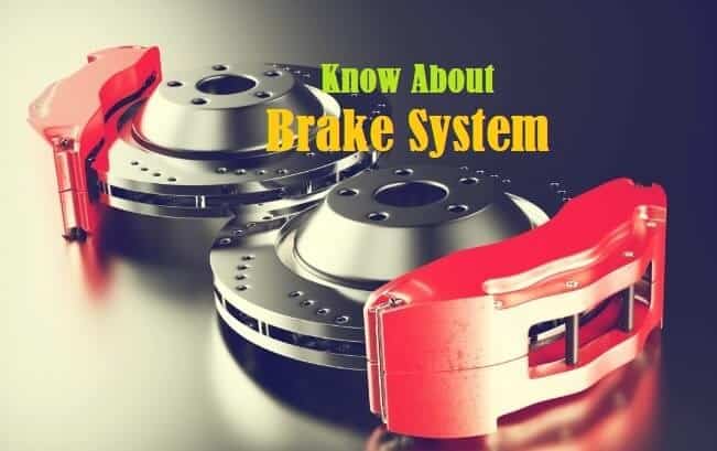

When someone asks “which is the brake in a car?”, they may be asking about the specific part that stops the vehicle. In reality, a car does not have only one brake component. The braking system is a group of mechanical, hydraulic, electrical and electronic components that work together to slow down or stop the vehicle.
The most visible part for the driver is the brake pedal. However, pressing the pedal activates a chain of components including the brake booster, master cylinder, brake fluid, brake lines, calipers, brake pads and rotors. Some vehicles use drum brakes, while modern vehicles commonly use disc brakes.
Understanding these components is important because braking is one of the vehicle’s most critical safety functions. The same principle of controlled energy conversion also appears in marine and industrial equipment, where motors, generators, control systems and automated machinery must safely control movement.
For a company such as Electrical Marine Solutions, understanding how mechanical systems interact with electrical control and automation is especially relevant when diagnosing complex equipment.
Quick Answer: Which Is the Brake in a Car?
The brake system is the group of components that slows or stops a car. When you press the brake pedal, force is transferred through the brake system to the wheels. In a typical modern car, the major braking components include the brake pedal, brake booster, master cylinder, brake fluid, brake lines, calipers, brake pads and brake rotors.
In simple terms, the brake pads press against the brake rotor in a disc-brake system. This creates friction that converts the car’s kinetic energy into heat, slowing the wheel and ultimately the vehicle.
Some cars use drum brakes, where brake shoes press against the inside of a rotating drum. Many vehicles use disc brakes on the front wheels and may use either disc or drum brakes at the rear.
Modern vehicles can also include anti-lock braking systems (ABS), electronic brake-force distribution and other electronic controls. These systems use sensors and control modules to help maintain braking stability.
Featured Snippet: What Part Actually Stops a Car?
In a typical disc-brake system, the brake pads and brake rotor are the components that create the friction needed to slow the wheel. When the driver presses the brake pedal, hydraulic pressure pushes the brake caliper against the rotor. The caliper squeezes the brake pads onto the rotor, producing friction and heat.
The brake pedal itself does not directly stop the car. Instead, it starts the braking process. The master cylinder converts pedal force into hydraulic pressure, while brake fluid carries that pressure through the brake lines.
The braking system therefore works as a complete chain:
Brake pedal → brake booster → master cylinder → brake fluid → brake lines → caliper → brake pads → rotor → wheel slows down.
In drum brakes, the final friction occurs between brake shoes and a brake drum instead.
This distinction is important when diagnosing brake problems because a symptom such as noise, vibration or poor stopping performance may originate from several different components rather than the pedal itself.
Key Takeaways
A car brake is not a single component. It is an integrated system designed to convert vehicle motion into heat through controlled friction. In modern disc-brake systems, the pads and rotor perform the primary friction function, while hydraulic and electronic components provide the necessary force and control.
The brake pedal is the driver’s input point. The master cylinder creates hydraulic pressure, and brake fluid transmits that pressure to the wheel-end components. The caliper squeezes the brake pads against the rotor.
Brake systems can use discs, drums or a combination of both. Modern vehicles may additionally use ABS sensors, electronic control units and other safety systems.
Regular inspection is essential because worn pads, contaminated brake fluid, damaged rotors, leaking hydraulic lines or electronic faults can reduce braking performance.
The same philosophy applies to marine and industrial engineering: reliable equipment depends on systematic inspection, accurate fault finding, preventive maintenance and properly functioning control systems.
What Is a Car Brake?
A car brake is a safety system designed to reduce the speed of a moving vehicle or bring it to a controlled stop. It works by creating resistance against the rotation of the wheels. In most modern vehicles, this resistance comes from friction between brake pads and rotating brake discs.
The braking system is designed around energy conversion. A moving car possesses kinetic energy. When the driver applies the brakes, the braking components create friction, converting much of that kinetic energy into heat. The vehicle therefore loses speed.
A conventional hydraulic braking system includes the pedal, brake booster, master cylinder, brake fluid, hydraulic lines and wheel-end braking components. Modern vehicles add electronic systems such as ABS, wheel-speed sensors and electronic stability controls.
The brake system must operate consistently under different loads, temperatures and road conditions. This is why brake inspection cannot be limited to checking whether the vehicle stops. Technicians must also assess component wear, hydraulic integrity, fluid condition, rotor condition and electronic operation.
From an engineering perspective, braking is an excellent example of a system in which mechanical components, fluid power and electronic controls must operate together. Similar system-level thinking is important in marine electrical troubleshooting, industrial automation and control-system maintenance.
How Does a Car Brake Work?
When the driver presses the brake pedal, the process begins with mechanical force. The pedal transfers this input to the brake booster and master cylinder. In a hydraulic braking system, the master cylinder converts the pedal movement into hydraulic pressure.
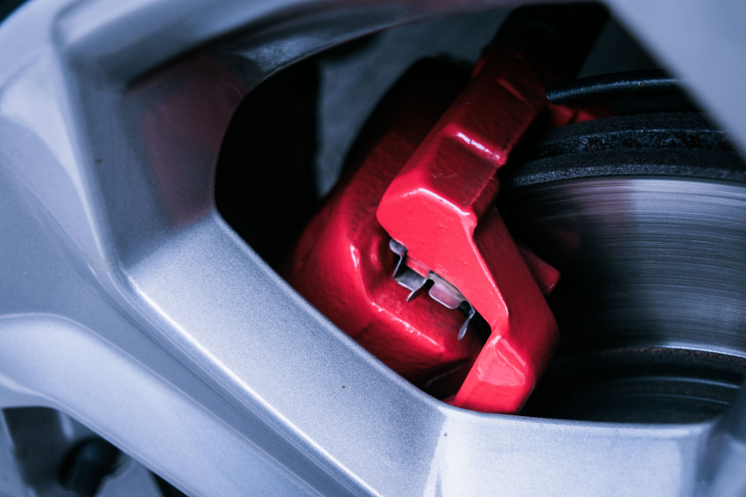
Brake fluid then travels through dedicated brake lines toward the wheels. At the wheel, the hydraulic pressure activates a brake caliper in a disc-brake system. The caliper pushes the brake pads against the rotating rotor.
The friction between the pads and rotor resists rotation. Because the rotor is connected to the wheel assembly, slowing the rotor slows the wheel. As all four wheels respond to braking force, the vehicle decelerates.
ABS adds another layer of control. Wheel-speed sensors monitor wheel rotation and allow the control system to reduce or restore hydraulic pressure when a wheel is approaching lock-up.
The process is therefore not simply “press pedal and stop.” It is a carefully engineered chain involving force transmission, hydraulic pressure, friction, heat generation, sensor feedback and electronic control.
This type of system-level approach is also valuable when engineers troubleshoot complex marine or industrial equipment. A fault in one component can affect the performance of an entire system, which is why professional diagnostics should follow a logical sequence rather than replacing parts randomly.
Major Components of a Car Brake System
A modern brake system contains several important components. Each has a specific role, and failure in one part can affect the performance of the complete system.
The brake pedal provides the driver’s input. The brake booster reduces the amount of physical effort required to generate braking force. The master cylinder converts pedal movement into hydraulic pressure.
Brake fluid carries hydraulic pressure through the brake lines. The lines and flexible hoses transport fluid to the wheel assemblies. In disc brakes, the caliper uses hydraulic pressure to press the brake pads against the rotor.
The rotor rotates with the wheel, while the pads remain stationary relative to the caliper. Their contact creates friction and heat.
In drum-brake systems, the main friction components are the brake shoes and brake drum. The shoes move outward against the internal surface of the rotating drum.
Modern vehicles may also contain ABS sensors, an ABS hydraulic modulator, electronic control units and warning sensors. These components help improve braking stability and provide diagnostic information.
Understanding each component makes troubleshooting easier. For example, a soft pedal may indicate hydraulic problems, while vibration may point toward rotor or wheel-related issues. Electronic warnings may require sensor or control-system diagnostics rather than mechanical replacement.
Disc Brakes vs Drum Brakes
Disc brakes and drum brakes both use friction to slow a vehicle, but their mechanical designs are different.
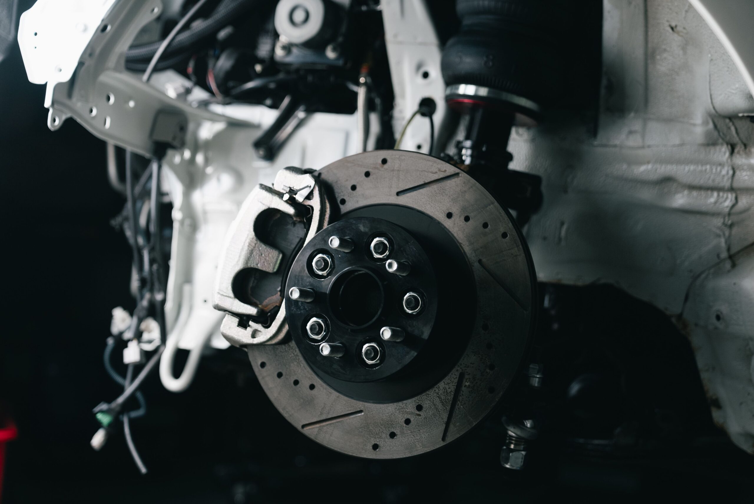
A disc brake uses a flat circular rotor attached to the wheel hub. A caliper surrounds part of the rotor, and brake pads are positioned inside the caliper. When hydraulic pressure is applied, the caliper pushes the pads against the rotor.
Disc brakes generally provide effective heat dissipation because the rotor is exposed to surrounding air. This makes them particularly common on front wheels, where braking loads can be significant.
A drum brake uses a cylindrical drum that rotates with the wheel. Brake shoes are located inside the drum. When the brakes are applied, the shoes move outward and contact the inner surface of the drum.
Drum brakes can be durable and cost-effective, although their enclosed design can make heat management and inspection different from disc systems.
Neither system should be judged solely by appearance. Correct design depends on vehicle specifications, load, operating conditions and manufacturer requirements.
For technical professionals, the important lesson is that different braking technologies require different inspection and maintenance procedures. The same principle applies to marine switchboards, motors, generators and automation systems: maintenance must match the actual equipment architecture.
What Happens When You Press the Brake Pedal?
Pressing the brake pedal initiates a sequence of mechanical, hydraulic and sometimes electronic events.
First, the driver’s foot applies force to the pedal. The pedal mechanism transfers this force toward the brake booster and master cylinder. The booster helps multiply the available force, making braking easier for the driver.
The master cylinder then creates hydraulic pressure. Brake fluid carries that pressure through the braking circuit to the wheel assemblies.
At a disc brake, hydraulic pressure causes the caliper piston or pistons to move. The brake pads are pushed against the rotor. Friction develops between the stationary pads and rotating rotor.
At the same time, vehicle electronics may monitor wheel-speed sensors. If ABS detects that a wheel is approaching lock-up, it can rapidly modulate braking pressure.
The driver experiences this entire process as a single action: pressing the pedal.
This illustrates why modern equipment maintenance increasingly requires both mechanical and electrical knowledge. A vehicle may have a mechanically healthy brake assembly but still experience a warning or control issue caused by an electronic sensor.
In marine environments, comparable interactions occur between electrical power, sensors, PLC programming, motors and control systems. Effective troubleshooting therefore depends on understanding how individual components communicate and influence the complete system.
Complete Brake Inspection Procedure
A professional brake inspection should begin with a visual and functional assessment before components are removed.
First, inspect the brake pedal for unusual travel, excessive softness or abnormal resistance. Next, inspect the brake fluid reservoir and look for low fluid level or contamination. Fluid loss may indicate a leak and should never be ignored.
Technicians should then inspect brake lines and flexible hoses for corrosion, cracking, leakage or physical damage. At the wheels, brake pads should be checked for remaining friction material and uneven wear.
Brake rotors should be examined for excessive scoring, cracks, abnormal wear patterns or heat-related damage. Calipers should be checked for leakage, seized pistons and uneven pad movement.
For drum brakes, technicians inspect the drum, shoes, springs, wheel cylinders and adjustment mechanisms.
The ABS system may require electronic diagnostic equipment. Fault codes, wheel-speed sensor readings and other system parameters can help identify intermittent faults that cannot be detected through visual inspection alone.
A proper inspection should also include a road or controlled functional test when safe and appropriate.
In professional engineering environments, inspection results should be documented. This creates a maintenance history and helps identify recurring problems. The same documentation approach is valuable for marine switchboards, generators, motors and industrial electrical systems.
Brake Testing Methods
Brake testing helps determine whether the braking system performs correctly under controlled conditions. Different tests are used depending on the vehicle and diagnostic requirement.
A basic functional test involves checking pedal response, braking stability and stopping behavior. Technicians may observe whether the vehicle pulls to one side, produces abnormal noise or requires excessive pedal force.
A visual inspection evaluates brake-pad thickness, rotor condition, fluid leakage and hardware condition.
Hydraulic testing can help identify pressure-related problems. If pressure is not developing correctly, the technician may investigate the master cylinder, brake lines, fluid or other hydraulic components.
Electronic diagnostics are increasingly important. A scan tool can identify ABS-related fault codes and help technicians examine sensor data.
Wheel-speed sensor testing may involve checking electrical signals, wiring continuity and sensor operation. Intermittent wiring faults can sometimes produce symptoms that appear mechanical but are actually electrical.
The exact testing procedure should follow the vehicle manufacturer’s service information and appropriate safety requirements.
The broader engineering principle is systematic verification. Whether troubleshooting an ABS sensor, marine generator, PLC-controlled motor or electrical switchboard, technicians should verify the fault before replacing expensive components. Accurate testing reduces unnecessary downtime and prevents repeated failures.
Common Brake Problems and Warning Signs
Brake problems often provide warning signs before a complete failure occurs. Recognizing them early can prevent dangerous situations and expensive repairs.
One common symptom is squealing or grinding noise. Squealing may have several causes, while grinding can indicate severe friction-material wear or another mechanical issue.
A soft or spongy brake pedal may indicate air or moisture in the hydraulic system, fluid problems or another braking-system fault. A pedal that feels unusually hard may involve the brake booster or related components.
Vehicle pulling to one side during braking can be associated with uneven braking force, caliper problems, contaminated friction material or other mechanical issues.
Brake vibration may be related to rotor condition, wheel components or other issues and should be professionally assessed rather than automatically attributed to one part.
A brake warning light or ABS warning light deserves immediate attention. Electronic warnings may indicate sensor, wiring, hydraulic or control-module issues.
Burning smells, visible fluid leaks, unusually long stopping distances or repeated brake-fluid loss are also important warning signs.
Drivers should not continue operating a vehicle normally when braking performance is significantly reduced. A qualified technician should determine the cause before the vehicle returns to service.
which is the brake in a car
Brake Troubleshooting Guide
Brake troubleshooting should follow a structured diagnostic process.
If the pedal feels soft, begin by checking brake-fluid level and inspecting the system for visible leaks. The hydraulic system may require further testing.
If the vehicle pulls during braking, inspect pad wear, caliper operation, rotor condition and related wheel components. Uneven braking force should be identified before replacing individual parts.
For brake noise, determine whether the sound occurs during light braking, heavy braking, turning or normal driving. The operating conditions can help narrow the diagnostic path.
If an ABS warning appears, scan the vehicle for diagnostic trouble codes and inspect wheel-speed sensors, connectors and wiring. Do not assume that replacing a sensor will solve every ABS problem.
If braking performance suddenly becomes poor, the vehicle should be treated as a safety-critical fault. It should not be operated unnecessarily until the system is inspected.
Professional troubleshooting is based on evidence. The technician should reproduce the symptom, inspect the relevant system, measure or test components, identify the root cause and verify the repair.
This root-cause methodology is equally important in Electrical Troubleshooting and Electrical Fault Finding. Random component replacement can waste time and money while leaving the original fault unresolved.
Brake Maintenance Best Practices
Preventive brake maintenance begins with regular inspection. Brake components gradually wear as the vehicle is operated, so waiting until a problem becomes obvious is not the best strategy.
Brake pads should be inspected according to the vehicle manufacturer’s recommendations and whenever abnormal symptoms appear. Rotors should be checked for wear and damage.
Brake fluid deserves particular attention. It can absorb moisture over time, and contaminated or degraded fluid can affect hydraulic performance. Fluid replacement intervals should follow the vehicle manufacturer’s specifications.
Brake hardware should also be checked. Sticking calipers, damaged hoses, corroded lines or improperly functioning components can cause uneven braking and accelerated wear.
Drivers should pay attention to changes in braking behavior. New noises, vibration, warning lights or pedal changes should be investigated promptly.
For fleets and commercial vehicles, preventive maintenance should be documented. Maintenance records help operators identify recurring problems and schedule work before failures cause unexpected downtime.
This philosophy is directly relevant to industrial and marine engineering. Preventive Maintenance programs for generators, motors, control systems and switchboards reduce unexpected failures and help equipment remain reliable.
Good maintenance is not simply about replacing worn parts. It is about understanding operating conditions, identifying early signs of degradation and maintaining the entire system systematically.
When to Repair or Replace Brake Components
The decision to repair or replace a brake component depends on its condition, specification, safety requirements and manufacturer’s recommendations.
Some components can be serviced or repaired when the underlying structure remains within acceptable limits. For example, certain hydraulic or mechanical components may be serviceable depending on the vehicle design.
However, components that are excessively worn, damaged, cracked, contaminated or outside specified limits may require replacement.
Brake pads are wear components and are normally replaced when their friction material reaches the manufacturer’s minimum acceptable level. Rotors may also require replacement if their dimensions or condition fall outside specification.
Brake hoses, lines, calipers and master cylinders require more detailed assessment because their failure can directly affect hydraulic braking.
Replacement should not be based only on appearance. A professional technician should compare measured condition against manufacturer specifications.
The same repair-versus-replacement principle applies to industrial equipment. A damaged motor, generator component, switchboard part or automation device may sometimes be repaired, while other conditions justify replacement.
For Electrical Marine Solutions, engineering decisions should be based on equipment condition, safety, reliability, lifecycle cost and operational requirements rather than simply selecting the cheapest immediate option.
Brake Safety Precautions
Brake systems are safety-critical equipment, so maintenance should never be approached casually.
Before servicing brakes, the vehicle must be securely immobilized. Proper lifting equipment and suitable support stands should be used when working beneath or around the vehicle.
Brake dust should be handled carefully, and technicians should follow appropriate workshop safety procedures. Hydraulic systems should not be opened unnecessarily, and only the correct brake fluid specification should be used.
After brake work, all relevant fasteners, hydraulic connections and components should be verified. The system may require bleeding or other procedures depending on the work performed.
A controlled functional test should be completed before returning the vehicle to normal operation.
Electrical safety is equally important in modern vehicles because braking systems may include sensors, electronic control modules and electrically controlled hydraulic systems.
In marine and industrial environments, safety requirements are even more demanding because equipment may involve high voltage, rotating machinery, generators and complex power distribution systems. Lockout/tagout procedures, isolation, verification and appropriate personal protective equipment are essential.
Whether working on a vehicle or a marine electrical installation, safety must take priority over speed.
Brake Systems in Commercial and Industrial Applications
Although the phrase “car brake” refers to automotive equipment, braking principles are used across many industries.
Commercial vehicles require braking systems capable of handling significantly greater loads and operating conditions than ordinary passenger cars. Heavy-duty applications may use different mechanical and pneumatic arrangements.
Industrial machinery can also require braking systems to safely stop rotating equipment. Motors, conveyors, cranes, winches and other machinery may use electrically controlled or mechanical braking systems.
Marine equipment presents another interesting application. Winches, cranes, propulsion-related machinery and rotating systems may require controlled stopping and holding functions.
In these applications, braking may interact with motors, generators, PLCs, sensors, control panels and power distribution systems.
A control system may command a motor to stop while a dedicated braking mechanism brings the rotating equipment to a controlled standstill. Safety interlocks may prevent operation when certain conditions are not satisfied.
This is where marine electrical engineering becomes particularly important. Reliable control depends not only on the mechanical brake but also on power supply integrity, wiring, sensors, PLC logic and control-system functionality.
Electrical Marine Solutions can apply this broader engineering mindset to marine and industrial equipment where electrical and mechanical systems operate together.
How Electrical and Electronic Systems Affect Braking
Modern braking systems increasingly depend on electronics. The traditional hydraulic brake remains important, but sensors and electronic control systems add monitoring and control capabilities.
ABS uses wheel-speed information to determine whether individual wheels are approaching lock-up. Electronic stability systems may also use steering, acceleration and wheel-speed information to help maintain vehicle stability.
These systems depend on reliable wiring, connectors, sensors, power supplies and control modules. A damaged wire or failed sensor can trigger warning lights or change system behavior.
This is why modern brake diagnostics can require both mechanical knowledge and electrical troubleshooting skills.
The same relationship is found in marine automation. A ship’s control system may rely on PLCs, sensors, actuators, motor controls and electrical distribution equipment. A failure in a sensor or communication circuit can produce symptoms that initially appear to be mechanical.
Professional fault finding therefore involves checking the entire system.
For marine environments, this can include Marine Automation, PLC Programming, Control Systems, Marine Switchboards, Power Distribution Systems and Electrical Fault Finding.
The key engineering principle is simple: diagnose the complete system rather than focusing only on the component where the symptom appears.
Why Trust Electrical Marine Solutions
Electrical Marine Solutions is positioned around professional marine and industrial electrical engineering, with services designed for complex operating environments where reliability, safety and technical accuracy matter.
The company’s expertise is relevant to Marine Electrical Services, Electrical Troubleshooting, Electrical Fault Finding, Marine Automation, Switchboard Maintenance, Generator and Motor Repairs, PLC Programming, Control Systems and Preventive Maintenance.
Experienced marine electrical engineers understand that equipment failures rarely occur in isolation. A motor problem may involve the power supply, starter, protection system, control circuit or PLC. A generator issue may involve excitation, monitoring, wiring or control logic. A switchboard fault may affect downstream equipment across an entire power-distribution network.
Professional diagnostic equipment helps engineers identify problems accurately instead of relying only on visual inspection.
Engineering best practices also emphasize safe isolation, structured testing, accurate documentation and root-cause analysis.
For commercial vessels, offshore platforms and other demanding environments, reliable technical support can reduce downtime and improve operational confidence.
The company can also support preventive maintenance strategies designed to identify potential failures before they become major operational problems.
For specialist marine and industrial electrical requirements, readers can explore Electrical Marine Solutions’ official website for further information.
Maintenance Checklist
A practical brake maintenance checklist should cover the complete system rather than only the brake pads.
Start by checking brake-pedal feel and travel. Inspect the brake-fluid level and look for visible leakage around the master cylinder, lines, hoses and wheel assemblies.
Inspect brake pads for wear and uneven contact. Examine rotors for abnormal scoring, cracks, excessive wear or other damage. Calipers should be checked for leakage and correct movement.
For drum brakes, inspect shoes, drums, springs and adjustment components.
Electronic systems should also be checked when warning lights appear. ABS sensors, wiring, connectors and diagnostic codes can provide important information.
After maintenance, confirm that the braking system operates correctly before returning the vehicle to normal service.
For commercial fleets, maintenance records should include inspection dates, component condition, work performed and follow-up requirements.
The same checklist philosophy can be extended to marine engineering. Preventive maintenance programs can include generator inspections, motor condition checks, switchboard maintenance, cable inspections, control-system verification and PLC diagnostics.
A documented checklist helps ensure that important steps are not forgotten and creates a useful history for future troubleshooting.
Inspection Checklist
A professional brake inspection should include the following areas:
- Brake pedal condition and travel
- Brake fluid level and condition
- Master cylinder
- Brake lines and flexible hoses
- Brake pads
- Brake rotors
- Brake calipers
- Brake shoes and drums where applicable
- Wheel-speed sensors
- ABS warning indicators
- Electrical wiring and connectors
- Unusual noise or vibration
- Vehicle pulling during braking
- Overall braking performance
Inspection should be performed using suitable equipment and manufacturer specifications.
For electrical components, technicians may use diagnostic scanners, electrical meters and other approved test equipment. Mechanical measurements should be compared with specified limits rather than relying on visual judgment alone.
In marine electrical environments, an equivalent inspection can cover switchboards, circuit breakers, protective devices, generator output, motors, control circuits, PLC inputs and outputs, communication networks and emergency systems.
Inspection quality depends on consistency. A good technician does not simply look for an obvious broken part. The objective is to understand the complete operating condition of the system and identify developing problems before they become failures.
Professional Tips From an Engineering Perspective
One of the most important professional tips is to never ignore a change in system behavior. Brakes may provide early warning through noise, vibration, pedal changes or warning lights.
Second, avoid replacing components based only on assumptions. Diagnose first, then repair.
Third, always use components and fluids that meet the correct specification. A visually similar component may not have the required performance characteristics.
Fourth, document recurring faults. Repeated failure of the same component may indicate an underlying issue such as incorrect installation, excessive operating temperature, contamination, electrical problems or poor system design.
Fifth, consider the entire system. Modern braking systems combine mechanical, hydraulic and electronic functions. A technician who checks only the mechanical parts may miss an electronic fault.
The same principle is critical in marine electrical engineering. If a motor repeatedly trips, simply resetting the breaker does not solve the root cause. Engineers must investigate load, insulation, protection, wiring, control logic and operating conditions.
Professional engineering is ultimately about safe diagnosis, reliable repair and prevention of repeat failures.
Real-World Example: Diagnosing a Brake Problem
Consider a vehicle whose driver reports that the car pulls to the right whenever the brakes are applied.
A poor diagnostic approach would immediately replace the brake pads. A structured approach begins by reproducing the symptom under safe conditions.
The technician then compares braking components on both sides. Pad wear, rotor condition and caliper movement are inspected. If one caliper is sticking, braking force may become uneven.
The technician should also consider other possible causes rather than assuming the brake system is solely responsible. Wheel, suspension and related mechanical conditions may need to be assessed.
If the vehicle has electronic brake controls, diagnostic information should also be reviewed.
Once the root cause is identified, the affected component can be repaired or replaced according to specification. A final functional test confirms whether the original symptom has been resolved.
This example demonstrates why experienced troubleshooting matters.
A similar scenario occurs on a commercial vessel when a motor repeatedly trips. The correct response is not simply to reset the breaker. Electrical engineers should investigate current draw, insulation, motor condition, protection settings, control logic and power quality.
The diagnostic philosophy is the same: identify the root cause before declaring the problem solved.
Future Trends in Brake Technology
Brake technology is becoming increasingly integrated with electronics, sensors and automated control.
Advanced driver-assistance systems are changing how vehicles detect hazards and respond to potential collisions. Electronic control systems can coordinate braking with stability, traction and driver-assistance functions.
Electric vehicles also create new braking requirements. Regenerative braking allows the electric drivetrain to recover some kinetic energy rather than converting all braking energy into heat through friction brakes.
This does not eliminate conventional brakes. Friction braking remains important for controlled stopping and situations where regenerative braking alone is insufficient.
Brake-by-wire technologies are also developing, with electronic systems playing a larger role in transmitting driver commands and managing braking force.
These trends demonstrate the increasing importance of electrical engineering in systems traditionally viewed as purely mechanical.
Marine and industrial equipment is undergoing a similar transformation. Automation, remote monitoring, PLCs, sensors, digital diagnostics and predictive maintenance are becoming increasingly important.
For marine electrical engineers, this means future maintenance will require strong knowledge of both electrical hardware and intelligent control systems.
Repair, Preventive Maintenance and Reliability Strategy
Reactive maintenance waits until something fails. Preventive maintenance schedules inspection and servicing before failure occurs. Predictive maintenance goes further by using condition data to identify potential problems.
For brake systems, preventive maintenance can identify worn pads, deteriorating fluid, damaged hoses and other problems before braking performance becomes unsafe.
In marine and industrial operations, the cost of unexpected failure can be much greater because equipment downtime may affect an entire operation.
A generator failure can interrupt essential power. A motor fault can stop production equipment. A switchboard issue can affect multiple circuits. A PLC or control-system failure can disable automated processes.
This is why preventive maintenance is not simply a cost. It is a reliability strategy.
Electrical Marine Solutions can support organizations requiring systematic Preventive Maintenance, Electrical Troubleshooting, Generator Maintenance, Motor Repairs, Switchboard Maintenance, Marine Automation and Industrial Electrical Engineering.
The objective is to keep equipment operating safely, identify degradation early and reduce unplanned downtime.
Conclusion
So, which is the brake in a car? The answer is that a car brake is an entire system rather than a single component.
The brake pedal starts the process, while the booster and master cylinder help generate hydraulic pressure. Brake fluid carries that pressure to the wheel assemblies. In disc brakes, calipers press brake pads against rotors, creating friction that slows the wheels. Drum brakes use brake shoes and drums instead.
Modern braking systems can also include ABS sensors, electronic control modules and other technologies that make braking safer and more controlled.
Understanding the complete system is essential for maintenance and troubleshooting. Noise, vibration, soft pedals, warning lights, fluid leaks and changes in braking behavior should never be ignored.
The same system-level approach applies to marine and industrial engineering. Reliable operations depend on properly maintained electrical systems, generators, motors, switchboards, PLCs, control systems and automation equipment.
If your vessel, offshore installation or industrial facility requires professional Marine Electrical Services, Electrical Troubleshooting, Electrical Fault Finding, Marine Automation, Generator Repairs, Motor Repairs, Switchboard Maintenance, PLC Programming, Preventive Maintenance or Industrial Electrical Engineering, contact Electrical Marine Solutions for technical support.
FAQs
1. Which part is the brake in a car?
The brake is a complete system rather than one individual part. In a disc-brake system, the brake pads and rotor create friction that slows the wheel. The pedal, booster, master cylinder, fluid, lines and caliper work together to transfer the driver’s braking command.
2. What happens when you press the brake pedal?
Pressing the brake pedal activates the braking system. The master cylinder generates hydraulic pressure, brake fluid transfers that pressure through the brake lines, and the calipers apply the brake pads against the rotors. Friction between the pads and rotors reduces wheel rotation and slows the vehicle.
3. Where are the brakes located on a car?
Braking components are located at the wheels. Disc-brake vehicles have rotors, calipers and pads around the wheel hubs. Vehicles with drum brakes have brake drums and shoes at the affected wheels. Additional components such as the master cylinder and brake booster are located in the engine-compartment area.
4. Are brake pads the brakes?
Brake pads are an important part of the braking system, but they are not the entire brake system. They create friction against the brake rotor in disc brakes. Other components, including the pedal, master cylinder, hydraulic lines and caliper, are necessary for the brake system to function.
5. What is the most important part of a brake system?
No single component can be considered the only most important part because braking depends on the complete system. However, brake pads, rotors, hydraulic components and electronic safety systems all have critical functions. A fault in any safety-critical component can reduce braking performance.
6. What are the main types of car brakes?
The two common mechanical designs are disc brakes and drum brakes. Disc brakes use rotors, calipers and pads, while drum brakes use drums and shoes. Modern cars may combine both types and may also use electronic systems such as ABS for improved braking control.
7. How do disc brakes work?
Disc brakes work by squeezing brake pads against a rotating metal disc called a rotor. Hydraulic pressure moves pistons inside the caliper, causing the pads to contact the rotor. Friction between the stationary pads and rotating rotor converts kinetic energy into heat and reduces vehicle speed.
8. How do drum brakes work?
Drum brakes contain brake shoes inside a rotating cylindrical drum. When the brake is applied, the shoes move outward and press against the inner surface of the drum. Friction between the shoes and drum slows the rotation of the wheel and therefore slows the vehicle.
9. What does ABS do?
ABS, or anti-lock braking system, helps prevent wheels from locking during hard braking. It uses wheel-speed information and electronic control to modulate brake pressure. This can help the driver maintain steering control during emergency braking, especially when road conditions provide uneven or limited traction.
10. Why does my brake pedal feel soft?
A soft or spongy brake pedal can have several causes, including air or moisture in the hydraulic system, fluid problems, leaks or other braking-system faults. Because braking is safety-critical, a significant change in pedal feel should be inspected by a qualified technician.
11. Why do brakes make a squealing noise?
Brake squealing can have several causes, including friction-material characteristics, contamination, wear, vibration or installation-related factors. The sound alone does not identify the exact problem. If squealing is persistent or accompanied by reduced braking performance, vibration or grinding, professional inspection is recommended.
12. Why does a car pull when braking?
A car can pull during braking when braking force is uneven between the wheels. Possible causes include caliper problems, uneven pad wear, contaminated friction material or other mechanical conditions. Suspension, steering and wheel-related issues may also need to be considered during diagnosis.
13. When should brake pads be replaced?
Brake pads should be replaced when their remaining friction material reaches the vehicle manufacturer’s specified limit or when they are damaged or contaminated. Uneven wear should also be investigated because it can indicate a caliper, hardware or other underlying problem requiring attention.
14. How often should brakes be inspected?
Brake inspection frequency depends on vehicle type, operating conditions, mileage and manufacturer recommendations. Brakes should also be inspected whenever symptoms such as unusual noise, vibration, pulling, warning lights or changes in pedal feel occur. Commercial and heavily used vehicles may require more frequent inspections.
15. Can a brake warning light be caused by an electrical problem?
Yes. Modern vehicles can use electrical sensors and electronic control systems for brake monitoring and ABS. A warning light may therefore be associated with a sensor, wiring, connector, control module or hydraulic issue. Diagnostic testing is needed to determine the actual cause.
16. What is the difference between a brake rotor and a brake pad?
A brake rotor is the rotating disc attached to the wheel assembly. A brake pad is a friction component that presses against the rotor when the brakes are applied. The interaction between the pad and rotor produces friction, converting kinetic energy into heat and slowing the vehicle.
17. Can brakes fail suddenly?
Brake performance can sometimes deteriorate rapidly, particularly when there is a major hydraulic failure, severe component damage or another critical fault. Regular inspection helps identify developing problems before they become serious. Any sudden loss of braking performance should be treated as an emergency safety issue.
18. Why is brake fluid important?
Brake fluid transfers hydraulic pressure from the master cylinder to the wheel-end braking components. If the fluid is contaminated, incorrectly specified, excessively degraded or leaking from the system, braking performance can be affected. Fluid should therefore be maintained according to the vehicle manufacturer’s requirements.
19. Can electrical troubleshooting help diagnose modern brake problems?
Yes. Modern braking systems can include ABS sensors, electronic control modules and wiring. Electrical troubleshooting can identify problems such as sensor failures, damaged wiring, poor connections and communication faults. Mechanical inspection should still be performed because brake problems can involve both electrical and mechanical systems.
20. Why is preventive maintenance important for braking systems?
Preventive maintenance identifies wear and developing faults before they become major failures. Regular inspection can detect worn pads, damaged rotors, hydraulic leaks, fluid deterioration and electronic faults. The same principle applies to marine electrical systems, generators, motors, switchboards and industrial automation equipment.