

If you are learning to drive, one of the first things you need to understand is the position of the pedals. A common beginner question is: what side is the brake on in a car? The answer is straightforward, but the exact pedal arrangement depends on whether the vehicle has an automatic or manual transmission.
In a standard left-hand-drive automatic car, the brake pedal is positioned to the left of the accelerator pedal. Both pedals are normally operated using the right foot. In a manual vehicle, the arrangement from left to right is generally clutch, brake, accelerator.
The brake pedal is one of the most important controls in a vehicle because it converts driver input into controlled deceleration. Pressing it activates a chain of mechanical, hydraulic, electrical and electronic systems that ultimately create friction at the wheels.
Although Electrical Marine Solutions focuses primarily on marine power and technical systems, understanding fundamental braking principles is useful for engineers working across automotive, marine and industrial environments. The same engineering concepts—control input, signal transmission, mechanical force, monitoring and fault diagnosis—appear in many modern electrical and automation systems.
Quick Answer: What Side Is the Brake On?
In most cars, the brake pedal is located between the clutch and accelerator on a manual vehicle, while in an automatic car it is normally to the left of the accelerator. Both pedals in an automatic car are generally operated with the right foot.
For a manual transmission, the pedals from left to right are usually:
Clutch → Brake → Accelerator
For an automatic transmission:
Brake → Accelerator
The brake pedal is usually wider than the accelerator, making it easier to identify and operate quickly. However, drivers should never rely only on pedal shape or position. Always become familiar with the specific vehicle before driving.
What Side Is the Brake On in a Car?
The brake pedal is normally the middle pedal in a manual car and the left pedal in an automatic car. In a manual vehicle, the order is usually clutch, brake and accelerator from left to right. In an automatic vehicle, there are normally only two pedals: the brake on the left and accelerator on the right. Both automatic-car pedals should normally be operated with the right foot.
Key Takeaways
The brake pedal is one of the most important controls in a vehicle. Remember these essential points before driving:
- In an automatic car, the brake is normally the left pedal.
- In a manual car, the brake is normally the middle pedal.
- The accelerator is normally positioned to the right of the brake.
- Manual vehicles usually have three pedals: clutch, brake and accelerator.
- Automatic vehicles normally have two pedals: brake and accelerator.
- The brake should normally be operated with the right foot in an automatic vehicle.
- Never operate the accelerator and brake simultaneously during ordinary driving.
- A soft, spongy or unusually hard pedal can indicate a braking-system problem.
- ABS helps maintain steering control during hard braking but does not eliminate stopping distance.
- Brake inspection should include the pedal, fluid, hydraulic system, pads, discs, calipers and electronic systems.
What Is the Brake Pedal?
The brake pedal is the driver’s primary control for slowing or stopping a vehicle. When a driver pushes the pedal, the input force is transmitted through the vehicle’s braking system until friction is produced at the wheels. This friction reduces wheel rotation and converts the vehicle’s kinetic energy primarily into heat.
Although the pedal itself looks simple, modern braking systems can involve several mechanical, hydraulic and electronic components. In a conventional hydraulic system, pedal movement operates a master cylinder that pressurizes brake fluid. The fluid travels through brake lines to calipers or wheel cylinders, which apply braking force.
Many modern cars also include a brake booster, anti-lock braking system, wheel-speed sensors and electronic control modules. These technologies improve braking assistance, stability and controllability.
From an engineering perspective, the pedal is an input device. The driver’s foot provides an input command, the braking system transmits and amplifies that command, and the wheel-end components produce the final mechanical effect.
This basic input-output relationship is similar to industrial and marine control systems. A switch, sensor or control input may initiate a sequence involving controllers, actuators and mechanical equipment. Proper troubleshooting therefore requires understanding the complete system rather than looking at one component in isolation.
Where Is the Brake Pedal Located?
The exact pedal arrangement depends primarily on the transmission type and vehicle design. In a typical automatic car, you will find two pedals in the driver’s footwell. The pedal on the left is the brake, while the pedal on the right is the accelerator.
In a manual car, there are generally three pedals. Looking from left to right, they are the clutch, brake and accelerator. The brake therefore occupies the middle position.
The brake pedal is usually wider than the accelerator because it is designed for frequent operation and quick identification. Some vehicles have distinctive pedal shapes, textures or markings to make identification easier.
Drivers should also understand that left-hand-drive and right-hand-drive vehicles do not normally reverse the basic relationship between brake and accelerator. The steering-wheel position changes, but the conventional pedal arrangement remains similar.
For a learner driver, it is good practice to sit in the driver’s seat with the engine switched off and identify each pedal before starting. Move your right foot between the accelerator and brake without pressing either pedal unnecessarily. In a manual vehicle, separately identify the clutch with your left foot.
This simple familiarization procedure can reduce confusion and help establish correct muscle memory.
Automatic vs Manual Pedal Layout
The main difference between automatic and manual vehicles is the presence of the clutch pedal. Automatic vehicles generally have two pedals, whereas manual vehicles normally have three.
| Vehicle Type | Left | Middle | Right |
|---|---|---|---|
| Automatic | Brake | — | Accelerator |
| Manual | Clutch | Brake | Accelerator |
In an automatic vehicle, the brake is the pedal on the left and the accelerator is on the right. Drivers generally use the right foot for both controls. This technique allows the driver to move the foot naturally between acceleration and braking while avoiding unnecessary simultaneous pedal operation.
In a manual car, the clutch is operated with the left foot. The right foot controls the brake and accelerator. During gear changes, the driver coordinates clutch movement with engine speed and vehicle speed.
One important point is that pedal layouts can vary slightly between specialist vehicles, modified cars and certain commercial applications. Therefore, anyone driving an unfamiliar vehicle should inspect the controls before moving.
The principle is especially important for fleet operators, commercial drivers and engineers who may work around different vehicle types. Familiarity should never be assumed simply because two vehicles appear similar.
How Does a Car Brake System Work?
A modern braking system works by converting driver-applied pedal force into controlled resistance at the wheels. When the driver presses the brake, the pedal moves a linkage or electronic sensing mechanism. In conventional hydraulic braking systems, this activates the master cylinder.
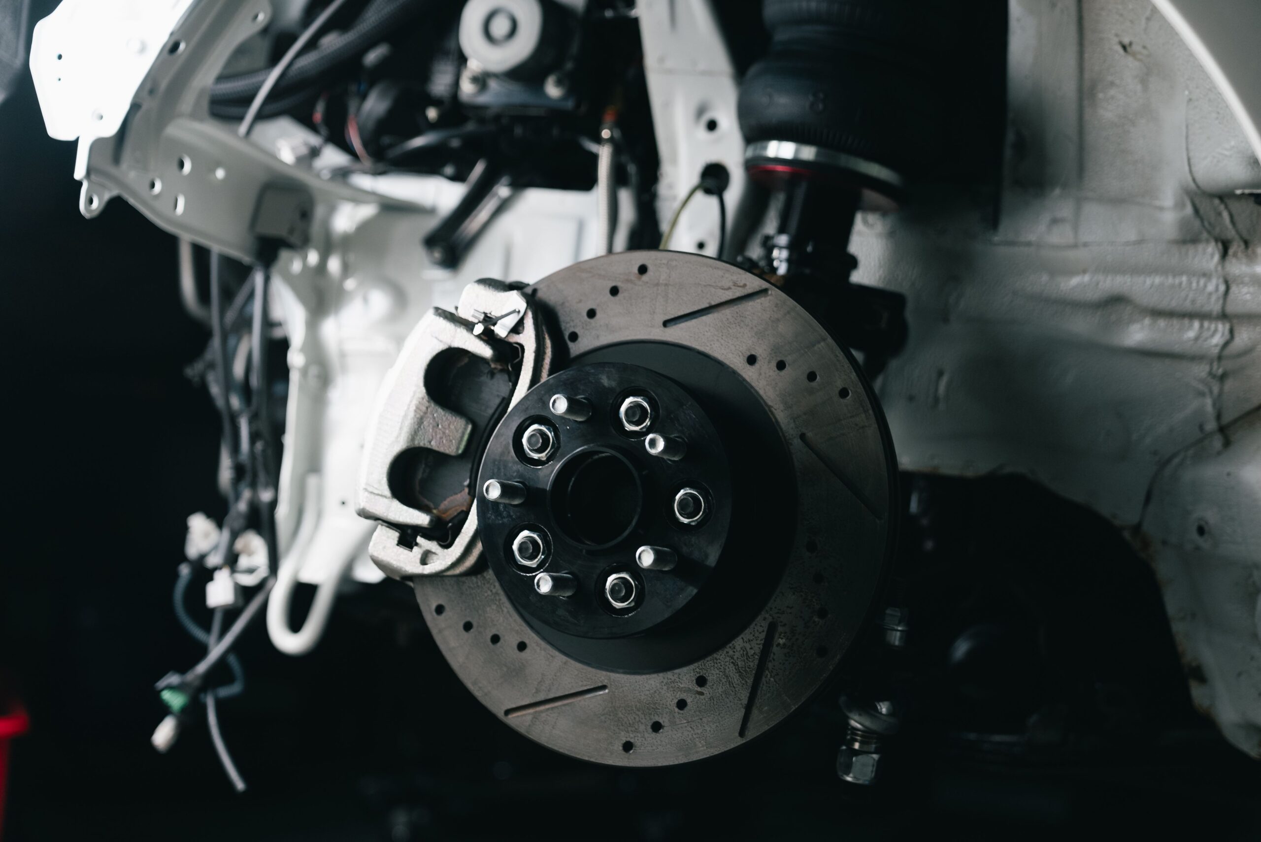
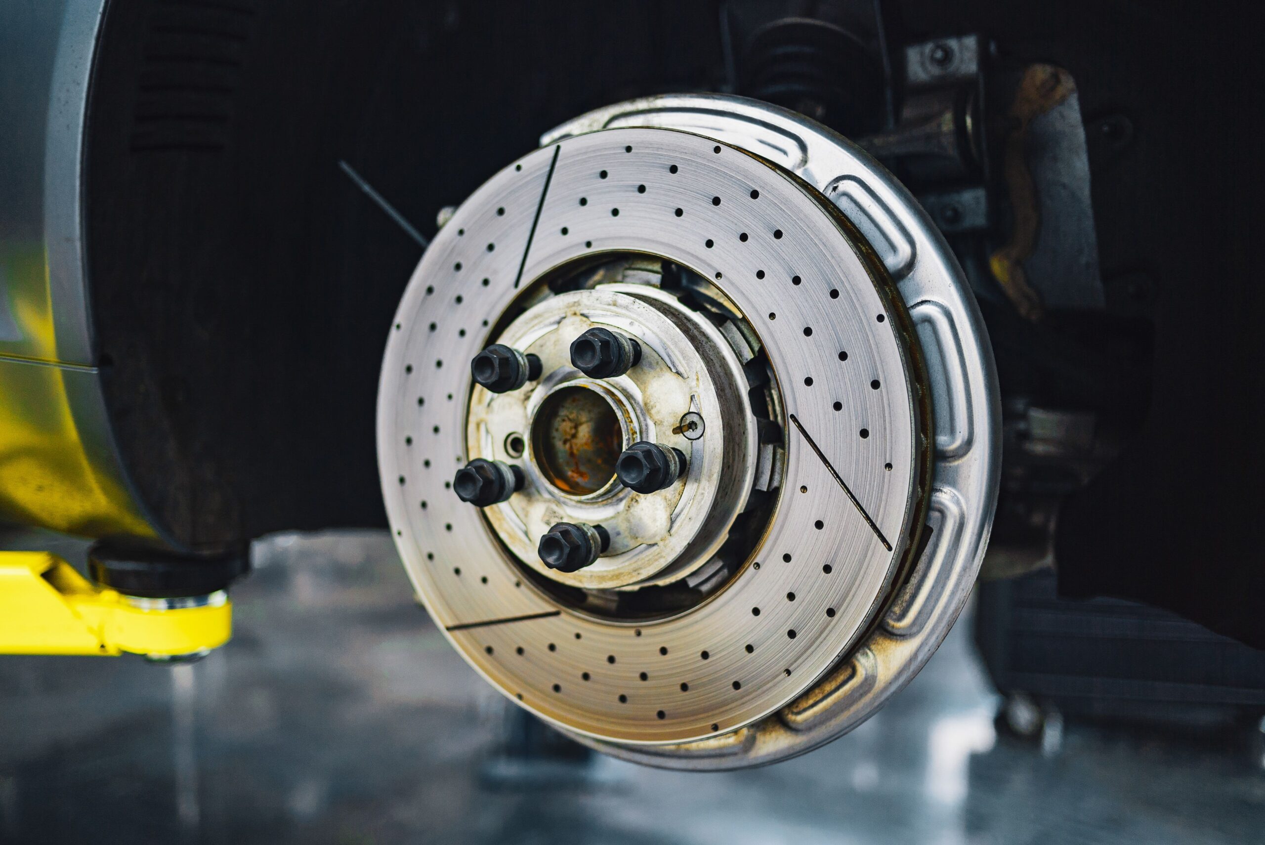
The master cylinder creates hydraulic pressure in the brake fluid. That pressure travels through brake pipes or hoses to the wheel-end assemblies. At the wheels, brake calipers squeeze brake pads against rotating discs, or wheel cylinders push brake shoes against brake drums.
The resulting friction slows the rotating wheels. Because the tires are in contact with the road, the reduction in wheel speed reduces the vehicle’s overall speed.
Brake boosters may multiply the driver’s input, making the system easier to operate. Modern vehicles may also use electronic systems that monitor wheel speed, brake pressure, vehicle motion and other parameters.
ABS is an important example. If the system detects that a wheel is approaching lock-up during heavy braking, it can rapidly modulate brake pressure. This helps maintain tire-road interaction and allows the driver to retain steering control.
From a systems-engineering perspective, braking is not simply a pedal-and-pad operation. It is a coordinated system involving mechanical force, fluid pressure, sensors, electronic control and physical friction.
Major Components of a Car Braking System
A braking system contains numerous components, and understanding their functions makes troubleshooting easier. The brake pedal is the driver’s input point. The brake booster can multiply pedal force, while the master cylinder converts mechanical input into hydraulic pressure.
Brake fluid carries pressure through the hydraulic circuit. Brake lines and flexible hoses transport that fluid toward the wheels. At each wheel, the braking hardware may include a caliper, pads and disc, or a wheel cylinder, shoes and drum.
Modern vehicles can also have ABS sensors positioned near the wheels. These sensors measure wheel rotation and send information to an electronic control module.
Other components include brake fluid reservoirs, pressure sensors, electronic parking-brake actuators and brake-light switches.
Each component has a specific role, but the system depends on all of them working together. A damaged hose, contaminated fluid, worn pad or faulty sensor can influence overall braking performance.
This is why professional electrical and technical troubleshooting often follows a structured diagnostic process. Rather than replacing components randomly, an engineer identifies symptoms, collects measurements, isolates the fault and verifies the repair.
The same philosophy is valuable in marine electrical troubleshooting, switchboard maintenance, generator systems and industrial automation. A systematic diagnostic method reduces downtime and avoids unnecessary component replacement.
How to Use the Brake Pedal Correctly
Correct pedal technique is essential for safe driving. In a typical automatic car, the right foot should normally be used to control both the brake and accelerator. The driver moves the foot between the two pedals according to whether acceleration or deceleration is required.
When approaching a stop, smoothly release the accelerator and apply progressive pressure to the brake. The amount of pressure required depends on speed, road conditions, vehicle weight and traffic conditions.
For a normal stop, braking should generally be controlled and progressive rather than unnecessarily abrupt. During an emergency, however, the driver may need to apply strong braking force immediately. Vehicles equipped with ABS are designed to manage wheel lock-up during hard braking.
Avoid resting your foot on the brake pedal while driving. Even light continuous pressure can generate unwanted heat and accelerate wear. It may also confuse drivers behind you because the brake lights can remain illuminated.
Do not develop a habit of using the left foot to brake in a conventional automatic vehicle unless a specific professional driving technique or vehicle configuration requires it.
Most importantly, learn the pedal positions before moving the vehicle. If you are unfamiliar with a car, locate the pedals, check the gear selector, adjust the seat and mirrors, and confirm that your foot placement feels natural.
Step-by-Step Braking Process
A normal braking event begins when the driver recognizes the need to reduce speed. The driver releases the accelerator and moves the right foot toward the brake pedal.
The driver then applies appropriate pressure. In a hydraulic system, pedal force moves the master-cylinder pistons and creates hydraulic pressure. The pressure travels through the brake circuit toward the wheel assemblies.
At the wheel, hydraulic pressure causes the caliper piston or wheel-cylinder mechanism to move. Brake pads or shoes then contact the rotating brake disc or drum.
Friction develops between these surfaces. This friction resists wheel rotation and converts kinetic energy into heat.
If the vehicle has ABS, wheel-speed sensors continuously monitor wheel rotation. When the control system detects a potential lock-up condition, it can modulate hydraulic pressure extremely rapidly.
As the vehicle slows, the driver can maintain or gradually reduce pedal pressure depending on the required stopping point.
After the vehicle stops, the driver keeps the vehicle secured using the appropriate transmission position and parking brake.
Understanding this sequence is useful when diagnosing a problem. For example, if pedal movement feels abnormal, the issue may be near the input side. If pedal feel is normal but braking force is weak, the fault could be hydraulic, friction-related, mechanical or electronic.
Brake Inspection and Testing Procedures
Brake inspection should be systematic. Start with the driver’s complaint and reproduce the symptom safely. A technician should never begin by replacing parts without understanding the problem.
The first inspection involves the pedal. Check pedal travel, resistance, return action and unusual noises. A pedal that suddenly feels soft or travels farther than normal requires immediate attention.
Next, inspect the brake-fluid reservoir and check for obvious leakage. Fluid condition and level should be evaluated according to the vehicle manufacturer’s specifications.
Wheel-end inspection should include brake-pad thickness, disc condition, caliper movement, hoses and signs of overheating. Uneven wear can provide valuable diagnostic information.
For vehicles equipped with ABS, electronic diagnostic equipment may be required. Fault codes, wheel-speed sensor signals and live data can help identify intermittent electrical problems.
Electrical testing should be performed carefully. Technicians may inspect sensor wiring, connectors, power supply, ground circuits and communication signals depending on the vehicle.
In professional environments, measurement results should be recorded. This creates a useful baseline for future preventive maintenance.
Electrical Marine Solutions applies the broader engineering principle of structured fault finding across marine and industrial systems: inspect, measure, isolate, repair and verify. This approach is particularly valuable when complex electrical controls interact with mechanical equipment.
Common Brake Problems and Warning Signs
A healthy braking system should provide predictable pedal feel and consistent stopping performance. Changes in braking behavior should never be ignored.
A soft or spongy pedal may indicate air or another hydraulic issue. A pedal that gradually sinks under steady pressure can indicate a hydraulic problem that requires professional inspection.
A hard pedal can sometimes indicate an issue with brake assistance, such as a vacuum-related problem in systems using vacuum assistance.
Grinding noises may indicate severe friction-material wear or another mechanical problem. A high-pitched squeal can have several causes, including pad material, wear indicators or vibration.
Vehicle pulling to one side during braking may indicate uneven braking force, a sticking caliper, tire problems or suspension-related issues.
Brake vibration can be associated with disc runout, uneven friction material or other mechanical conditions.
An illuminated ABS warning light does not necessarily mean the basic brakes have completely failed, but it indicates that an electronic safety system requires attention.
Other warning signs include unusual brake-fluid loss, burning smells, overheating wheels and increased stopping distance.
Because braking is a critical safety system, drivers should treat significant changes as faults rather than normal wear.
Brake Troubleshooting Guide
Brake troubleshooting should begin with symptoms rather than assumptions. A professional technician first identifies exactly what the driver experiences.
If the pedal is soft, inspect fluid level, leaks, hydraulic integrity and possible air contamination. If the pedal is hard, inspect the brake-assistance system and related components.
If the vehicle pulls left or right, compare wheel-end conditions, caliper operation, pad wear, tire condition and suspension components.
For grinding or scraping, inspect friction components immediately. Continuing to drive with severely damaged braking components can increase repair costs and create a safety risk.
If ABS activates unexpectedly, inspect wheel-speed sensors, tone rings, wiring, sensor alignment and electronic diagnostic data.
Intermittent electrical faults require additional care. A technician may need to perform continuity checks, voltage measurements, connector inspections and live-data monitoring.
The key principle is to avoid guessing. Fault codes can provide useful information but should not automatically be interpreted as proof that a specific component must be replaced.
This diagnostic mindset is equally relevant to marine electrical fault finding. A generator that fails to start, a motor that trips or a PLC-controlled system that behaves intermittently may involve multiple possible causes. Good troubleshooting follows evidence rather than assumptions.
Brake Maintenance and Preventive Inspection
Preventive maintenance can identify developing brake problems before they become serious. The inspection frequency should always follow the vehicle manufacturer’s recommendations, operating conditions and local requirements.
Brake pads and discs should be inspected for wear. Hydraulic hoses should be checked for cracking, abrasion or leakage. Brake fluid should be replaced according to the manufacturer’s service interval and specification.
Wheel-end components should be kept clean and correctly installed. Fasteners must be tightened according to specified torque requirements.
ABS sensors and wiring should be inspected when relevant, especially after suspension, wheel or brake work.
Vehicles used in heavy-duty conditions may require more frequent inspections. Frequent towing, mountainous driving, high loads, commercial operation and repeated heavy braking can increase thermal and mechanical stress.
A preventive-maintenance program should document inspection dates, observed conditions, measurements and repairs.
This philosophy extends naturally to industrial and marine environments. Preventive maintenance of switchboards, generators, motors, control systems and power-distribution equipment reduces unexpected downtime.
For commercial vessels and offshore operations, planned maintenance is especially important because electrical or mechanical failures can affect propulsion, auxiliary systems, safety equipment and operational continuity.
Safety Precautions When Working on Brake Systems
Brake work should be treated as safety-critical maintenance. Before beginning any repair, secure the vehicle properly and follow the manufacturer’s service procedures.
Never rely solely on a hydraulic jack to support a vehicle. Use appropriate supports and ensure the vehicle cannot move unexpectedly.
Wear suitable eye protection and gloves when performing maintenance. Brake components can contain dust, corrosion and contaminants.
Use only the correct brake fluid specified for the vehicle. Different fluid types should never be mixed unless the manufacturer specifically permits it.
Do not reuse damaged brake hoses, compromised hardware or components that fail inspection requirements.
After brake work, the system should be tested under controlled conditions before normal road use. The technician should confirm pedal feel, fluid integrity, braking response and any electronic warning indicators.
Electronic brake and ABS systems may require specialized diagnostic procedures after certain repairs.
For professional engineers, safety also means controlling energy sources. Electrical and hydraulic energy can both create hazards. Marine and industrial maintenance therefore commonly relies on isolation procedures, verification and controlled restoration of power.
Safety should always take priority over speed when repairing critical systems.
what side is the brake on in a car
Repair vs Replacement: What Should You Choose?
Whether a brake component should be repaired or replaced depends on its condition, design and manufacturer requirements. Some components can be serviced, while others are generally replaced as complete assemblies.
Brake pads are wear components and are normally replaced once they reach the manufacturer’s minimum thickness or show unacceptable damage.
Discs may sometimes be resurfaced where permitted and where sufficient material remains. However, replacement may be appropriate if the disc is below minimum thickness, severely damaged or otherwise outside specification.
Brake calipers may be rebuilt in certain applications, but replacement can be more practical when corrosion, piston damage or other major defects are present.
Electrical components such as ABS sensors may sometimes be repairable at the wiring level, while a failed sensor itself may require replacement.
The important principle is not simply repair versus replacement. The decision should consider safety, reliability, manufacturer specifications, labor, parts availability and long-term operating cost.
In marine engineering, the same decision process applies to motors, generators, control modules and switchboard components. A low-cost repair that repeatedly fails may be more expensive than a correct replacement.
Professional maintenance should therefore focus on lifecycle reliability rather than the lowest immediate repair price.
Brake System Cost Factors
Brake service costs vary significantly depending on the vehicle, components, labor rates and extent of the repair. A basic inspection may be relatively inexpensive, while replacing multiple wheel-end components can cost substantially more.
The main cost factors include brake-pad type, disc or drum condition, caliper requirements, hydraulic repairs, brake-fluid service, ABS diagnostics and labor.
Specialized vehicles, performance cars and commercial vehicles may use more expensive components.
Electrical diagnosis can also affect cost when ABS or electronic brake-control systems are involved. A technician may need specialized scan equipment, electrical testing instruments or manufacturer-specific procedures.
Drivers should be cautious of quotes that identify a component without explaining the diagnostic evidence. A professional estimate should ideally explain what has failed, why replacement is necessary and what additional work is recommended.
For fleet and industrial operators, total lifecycle cost is more useful than looking only at individual repair invoices. Preventive inspection, scheduled servicing and condition monitoring can reduce unplanned downtime.
The same approach applies to marine assets. A planned generator maintenance program or switchboard inspection can help prevent costly operational interruptions. Reliability engineering considers the cost of failure, not merely the cost of maintenance.
Brake Technology and Future Trends
Vehicle braking technology continues to evolve as manufacturers introduce more electronic control, regenerative braking and automated driving functions.
Electric and hybrid vehicles may combine conventional friction brakes with regenerative braking. During regenerative braking, the electric motor can operate as a generator and recover some kinetic energy.
Brake-by-wire systems can reduce the direct mechanical relationship between the driver’s pedal and conventional hydraulic components. Sensors and electronic controllers interpret driver input and command braking force.
Advanced driver-assistance systems can also interact with braking. Automatic emergency braking, adaptive cruise control and stability-control systems rely on sensors and electronic control algorithms.
These developments increase the importance of electrical troubleshooting and control-system expertise.
The same technological direction can be seen in marine engineering. Modern vessels increasingly rely on integrated automation, PLC-based control, electronic monitoring, variable-speed drives, digital instrumentation and sophisticated power-management systems.
Electrical Marine Solutions’ marine-power and technical orientation is therefore relevant to the broader transition toward electronically controlled equipment. The engineering fundamentals remain the same: accurate sensing, reliable control, safe power distribution, fault detection and effective preventive maintenance.
Applications Across Automotive, Marine and Industrial Engineering
Braking is primarily associated with road vehicles, but the engineering concept of controlled deceleration appears across many industries.
Commercial vehicles use braking systems designed around vehicle mass, operating environment and duty cycle. Heavy equipment may use hydraulic, pneumatic or electronic braking technologies.
Marine vessels can use mechanical and electro-hydraulic systems for winches, cranes, propulsion controls and other equipment where controlled movement is required. Offshore platforms similarly depend on engineered control systems for safe machinery operation.
Industrial facilities use motors, drives, brakes and control systems to control conveyors, cranes, lifting equipment and rotating machinery.
This is where marine electrical engineering and automotive technology share valuable principles. Both require reliable control signals, properly sized components, protective systems and structured troubleshooting.
Electrical Marine Solutions supports the broader marine engineering environment through technical consultation, marine installation and marine power expertise. Its current website describes experience in marine electrical systems and support for ships, yachts and offshore installations.
For engineers, understanding one controlled system can strengthen the ability to diagnose another because the underlying concepts—input, control, feedback, actuation and protection—are closely related.
Why Trust Electrical Marine Solutions
Electrical Marine Solutions presents itself as a marine-focused technical company with experience in marine electrical systems, marine power and installation support. Its website states that the company was founded in 2016 by three owners with more than 20 years of hands-on experience in the maritime electrical sector. This level of technical experience reflects the importance of understanding equipment controls, just as drivers need to know what side is the brake on in a car before operating a vehicle.
For marine operators, technical experience matters because shipboard electrical systems are rarely isolated. Generators, motors, switchboards, automation equipment, control systems and power distribution networks operate together. In the same way that knowing what side is the brake on in a car helps a driver operate the vehicle safely, understanding how individual marine electrical components interact is essential for reliable vessel operation.
A competent marine electrical team should therefore understand both individual components and system-level interactions. Diagnostic work should involve inspection, measurement, fault isolation and verification rather than guesswork. This systematic approach is similar to understanding what side is the brake on in a car before examining the wider braking system and its components.
Electrical Marine Solutions’ published services and technical positioning make it relevant to vessel owners, marine professionals and operators seeking support with marine installations and power-related engineering requirements. The company’s technical approach also demonstrates why clear identification of controls, such as what side is the brake on in a car, is an important part of safe equipment operation.
For more complex requirements such as Marine Electrical Services, Electrical Troubleshooting, Marine Automation, generator support, switchboard maintenance, PLC Programming, Preventive Maintenance and Industrial Electrical Engineering, customers should confirm the exact scope of work with the company before scheduling a project. Just as a driver should understand what side is the brake on in a car, marine operators should understand the function and operating requirements of critical electrical equipment.
This emphasis on technical consultation is particularly valuable for equipment selection, compatibility assessment, installation planning and troubleshooting. Understanding what side is the brake on in a car may seem like a basic concept, but it illustrates a broader engineering principle: operators must clearly understand controls before using technical equipment.
The same principle applies when engineers inspect marine automation, control systems, generators and power distribution equipment. Before any system is commissioned, professionals should verify that controls, signals and protective functions operate correctly. In this context, knowing what side is the brake on in a car represents the simplest example of correct control identification.
Ultimately, safe operation depends on knowledge, verification and proper procedures. Whether a driver is learning what side is the brake on in a car or a marine engineer is commissioning a complex electrical installation, understanding how the system works before operating it is fundamental to safety, reliability and effective maintenance.
Maintenance Checklist
A practical brake maintenance checklist should begin with the driver’s observations. Record any changes in pedal feel, stopping distance, noise, vibration or vehicle behavior. Before starting the inspection, confirm what side is the brake on in a car so the driver can correctly identify the brake pedal.
Inspect the brake-fluid reservoir and look for evidence of leakage. Examine visible hoses and connections for damage. Check pads and discs for wear where accessible. Understanding what side is the brake on in a car is also useful when performing a basic pedal-function check after maintenance.
Inspect tires because braking performance depends heavily on tire-road contact. Uneven tire condition can sometimes be mistaken for a braking fault. Drivers should also know what side is the brake on in a car before conducting any controlled test.
Check the operation of brake lights and investigate dashboard warning indicators. During a pre-drive inspection, verify what side is the brake on in a car and make sure the driver is familiar with the pedal layout.
For vehicles with ABS or electronic brake systems, scan for diagnostic codes when appropriate. Electronic diagnostics can help identify faults that are not immediately visible, while knowing what side is the brake on in a car helps ensure correct pedal identification during functional testing.
After maintenance, perform a controlled functional test and confirm that the pedal feels normal. The driver should already understand what side is the brake on in a car before the vehicle begins moving.
For professional fleet operators, document every inspection. Include mileage, date, measured component condition and corrective action. Training drivers on what side is the brake on in a car can also help reduce pedal confusion when vehicles are shared between multiple operators.
A similar checklist philosophy can be used in marine preventive maintenance. Generator condition, motor insulation, switchboard connections, control-system signals and protection devices should be inspected according to an appropriate maintenance schedule. Documentation is not simply administrative. It creates historical data that can help engineers identify recurring failures and predict maintenance requirements. The same principle of clearly identifying controls applies when engineers evaluate what side is the brake on in a car or troubleshoot more complex marine and industrial equipment.
Inspection Checklist
Before operating a vehicle after brake maintenance, confirm the brake pedal has normal travel and resistance. Understanding what side is the brake on in a car should be part of the basic pre-driving check, especially when a vehicle has recently been serviced.
Check that there are no visible hydraulic leaks and confirm that you can correctly identify what side is the brake on in a car before moving the vehicle. This is particularly important when operating an unfamiliar vehicle after maintenance.
Confirm that brake components have been installed correctly and that required fasteners are properly secured according to manufacturer specifications. Knowing what side is the brake on in a car helps ensure the driver does not confuse the brake pedal with the accelerator during the initial functional test.
Check the condition of friction surfaces and ensure that components are not contaminated with oil, grease or unsuitable materials. As part of this inspection, verify what side is the brake on in a car and make sure the driver understands the pedal layout.
Verify that wheels are correctly installed and tightened according to specification. Before conducting a road test, confirm what side is the brake on in a car so the driver can respond correctly if braking is required.
Where required, inspect ABS sensors, wiring and connectors. Electronic braking systems can depend on accurate sensor signals, making it important to understand both the braking hardware and what side is the brake on in a car.
Confirm that warning lights behave correctly after system initialization. Conduct a controlled test at low speed before returning the vehicle to normal operation, while ensuring the driver knows what side is the brake on in a car and can operate the pedal confidently.
For electronic systems, verify relevant diagnostic data and clear fault codes only after the underlying problem has been resolved. The same inspection philosophy applies to industrial electrical work. After a repair, engineers should not simply restore equipment and walk away. Functional testing, protection verification and documentation are essential. For marine installations, commissioning should confirm that equipment performs correctly under appropriate operating conditions before the vessel returns to service. Understanding what side is the brake on in a car is a simple example of the broader engineering principle of verifying controls before equipment is placed back into operation.
Professional Tips From a Systems-Engineering Perspective
Tip 1: Learn the controls before moving. If you are driving an unfamiliar vehicle, identify the pedals and controls before starting.
Tip 2: Do not diagnose by appearance alone. A clean-looking brake component can still have an internal fault.
Tip 3: Treat unusual pedal feel seriously. Sudden changes deserve professional inspection.
Tip 4: Use measurement wherever possible. Diagnostic evidence is more reliable than assumptions.
Tip 5: Do not ignore electronic warnings. ABS and other control-system alerts can indicate faults that require scanning.
Tip 6: Think about the entire system. A brake problem may involve hydraulic, mechanical, electrical or electronic components.
Tip 7: Prioritize reliability. The cheapest immediate repair is not always the lowest-cost solution over the equipment’s lifecycle.
Tip 8: Document maintenance. Historical records make recurring fault patterns easier to identify.
These principles are equally valuable in marine electrical engineering. Whether troubleshooting a generator, motor, PLC-controlled system, switchboard or power-distribution network, the strongest diagnostic approach is systematic and evidence-based.
FAQs
1. What side is the brake on in an automatic car?
In a conventional automatic car, the brake pedal is normally the left of the two pedals, while the accelerator is on the right. Both pedals are generally operated with the right foot. Always familiarize yourself with the pedal arrangement before driving an unfamiliar vehicle.
2. Which pedal is the brake in a manual car?
In a standard manual car, the brake is the middle pedal. From left to right, the pedals are normally clutch, brake and accelerator. The left foot operates the clutch, while the right foot operates the brake and accelerator.
3. Is the brake pedal on the left or right?
It depends on the transmission. In an automatic car with two pedals, the brake is normally on the left and the accelerator is on the right. In a manual car, the brake is positioned between the clutch and accelerator.
4. What pedal do you press to stop a car?
You press the brake pedal to slow or stop a car. In an automatic vehicle, it is normally the wider pedal on the left. Apply appropriate pressure based on the situation, road conditions and required stopping distance.
5. Which pedal is the accelerator?
The accelerator is normally the pedal on the far right. It controls engine or powertrain output and increases vehicle speed when pressed. Drivers should use controlled pedal movement and avoid confusing it with the brake.
6. Do automatic cars have a clutch pedal?
Most conventional automatic cars do not have a driver-operated clutch pedal. They normally have two pedals: the brake and accelerator. The transmission manages gear changes internally through its automatic transmission system.
7. Should you use your left foot to brake?
For conventional automatic driving, drivers are generally taught to use the right foot for both braking and acceleration. This reduces the likelihood of accidentally pressing both pedals and provides a consistent driving technique.
8. Why is the brake pedal wider than the accelerator?
The brake pedal is commonly wider because it is a critical control that must be easy to identify and operate. Its shape can help distinguish it from the accelerator, particularly during normal driving and emergency situations.
9. What does a soft brake pedal mean?
A soft or spongy brake pedal can indicate a hydraulic problem, air in the braking system, fluid issues or another fault. Because braking is safety-critical, a significant change in pedal feel should be professionally inspected before continued normal use.
10. What does a hard brake pedal mean?
An unusually hard pedal can sometimes indicate a problem with the brake-assistance system. The exact cause depends on the vehicle design. A professional technician should inspect the system rather than assuming the pedal itself is defective.
11. Why does my car pull when braking?
A vehicle may pull to one side because of uneven braking force, a sticking caliper, uneven pad wear, tire problems or suspension-related issues. The system should be inspected because pulling can affect vehicle stability and stopping behavior.
12. Why do brakes make grinding noises?
Grinding can indicate severe friction-material wear or metal-to-metal contact, although other mechanical conditions can also produce similar sounds. Continued driving without inspection can cause additional component damage, so persistent grinding should be investigated promptly.
13. What does the ABS light mean?
The ABS warning light indicates that the anti-lock braking system has detected a fault or abnormal condition. The conventional braking system may still function, depending on the fault, but the vehicle should be inspected to determine why the warning appeared.
14. How often should brakes be inspected?
Brake inspection frequency depends on the vehicle, mileage, operating conditions and manufacturer recommendations. Vehicles used heavily, for towing or in demanding environments may require more frequent checks. Routine inspection is preferable to waiting for obvious failure symptoms.
15. Can brake pads be repaired?
Brake pads are normally wear components and are replaced rather than repaired when worn beyond specification. If contamination, uneven wear or mechanical damage occurs, the cause should also be identified before installing new pads.
16. How do hydraulic brakes work?
Hydraulic brakes use brake fluid to transmit pressure from the master cylinder to wheel-end components. When the driver presses the pedal, hydraulic pressure causes calipers or wheel cylinders to apply friction material against discs or drums.
17. Does ABS make a car stop instantly?
No. ABS does not eliminate stopping distance. Its main purpose is to help prevent wheel lock-up during hard braking and preserve steering control. Stopping distance still depends on speed, tires, road surface, vehicle condition and driver response.
18. Can electrical faults affect braking?
Yes. Modern vehicles use electronic systems for ABS, stability control, sensors and other functions. Wiring faults, damaged sensors, poor connections or control-module problems can affect electronic braking functions and may require specialized diagnostic equipment.
Conclusion
Knowing what side is the brake on in a car is a basic driving skill, but understanding the engineering behind the pedal provides a much deeper appreciation of vehicle safety. For new drivers, learning what side is the brake on in a car can help build confidence before operating an unfamiliar vehicle.
In a typical automatic vehicle, what side is the brake on in a car is generally answered by identifying the left pedal as the brake and the right pedal as the accelerator. In a manual vehicle, the brake is normally the middle pedal between the clutch and accelerator. Understanding what side is the brake on in a car is especially important for learner drivers who are still developing correct pedal control.
The pedal is only the beginning of a much larger system. Brake boosters, master cylinders, hydraulic circuits, calipers, pads, discs, sensors and electronic control systems must work together to produce predictable braking performance. Understanding what side is the brake on in a car is therefore only the first step toward learning how the complete braking system operates.
Drivers should become familiar with pedal positions before operating an unfamiliar vehicle and should never ignore abnormal pedal feel, warning lights, unusual noises, fluid loss or changes in stopping performance. If you are learning what side is the brake on in a car, take time to identify the brake and accelerator before starting the engine.
The same engineering mindset applies beyond automotive systems. Marine vessels, offshore platforms and industrial facilities increasingly depend on interconnected electrical, mechanical and automated equipment. Effective maintenance requires accurate inspection, structured troubleshooting, reliable control and preventive planning. The basic question of what side is the brake on in a car also demonstrates the importance of clearly understanding an equipment’s controls before operation.
Electrical Marine Solutions operates within this wider marine engineering environment, with its published expertise covering marine electrical systems, marine power and installation-related technical support. The company’s engineering approach reflects the same principle involved in understanding what side is the brake on in a car: operators and engineers need to understand how individual controls connect to a complete technical system.
For professional requirements involving Marine Electrical Services, Electrical Troubleshooting, Marine Automation, Generator Repairs, Switchboard Maintenance, PLC Programming, Preventive Maintenance or Industrial Electrical Engineering solutions, professional technical assessment is the safest approach. Whether you are researching what side is the brake on in a car or troubleshooting a complex marine electrical system, accurate technical knowledge is essential.
Learning what side is the brake on in a car should be combined with understanding proper braking technique, pedal operation and vehicle safety. Once drivers know what side is the brake on in a car, they can focus on developing smooth braking habits and recognizing potential warning signs before they become serious problems.

